
This and the next article will present localization in buildings using wireless networks. Let’s start with multilateration that is used by the army, for example. How does it work, how can we use it and what should we look out for?
Localization with a to-the-room accuracy fast and easy (3/4)
The last article introduced Dead Reckoning. It’s based on saving the deviations from a given starting point and does not need any network to operate. As promised, these two articles will focus on the localization methods based on receiving a signal from various wireless networks.
Kopac and three beautiful ladies
You know what radar is. You can see it at almost every airport and its task is simple: to detect flying objects. To be able to do this, the radar has to “send out” waves that bounce off a given object. This feature can be used in a military conflict to discover if an enemy is using radar.
There are passive systems that try to prevent the detection of radar. These don’t send out waves, they only listen on a given frequency band. If an aircraft flies over this locator, its transmissions, e.g. communication, are intercepted. Using other locators nearby, you can determine the position of the airplane. Please note that for this method it does not matter what is being transmitted. The content of the transmission is not important.
In the Czech Republic, the development of passive radars started in the 1960s and the first one was called Kopac (Digger). Kopac was followed by Ramona, Tamara, and the most recent one is Vera. An interesting fact about this method is that it can detect even “invisible” aircraft (Stealth aircraft). To get detected, all it needs to do is communicate with its surroundings.
Let’s do it the other way around
Passive radars are, in fact, just big ears listening and waiting to record any transmission generated by aircraft. In other words, it’s a collection of several receivers and only one transmitter. We can’t just copy this concept to an environment with access points and phones as that would allow us to find out only where the access point is. But we want to know where the phone and its user are.
We are in a different situation. We need to determine the receiver’s location using a couple of access points. How many access points do we need? To calculate the number necessary, we need to understand how the signal spreads from the access point.
Circles and spheres
This is my favourite part – math. Don’t worry, it won’t be difficult. The signal emitted by the access point spreads to all directions in an open space. Therefore we can imagine a sphere around the access point that shows its range.
To make the calculations even simpler, let’s use a two-dimensional Cartesian space. That’ll make a circle out of the sphere. But we don’t mind as we know the equation that describes the circle:

Sounds familiar, right? Basically it’s the Pythagorean theorem. The circle is defined as the set of all points that are at the same distance from the centre. This centre has the coordinates defined as [m,n] and a point on the circle has the [x,y] coordinates. If we use these points to create a vector, we’ll get the circle’s radius r.
Why is this useful? The r does not have to be the maximum possible range of the access point. It can be the receiver’s distance from the access point. To determine this distance, we’ll use the signal’s strength. Then, the circle’s centre is the location of the access point.
We know how to note the access point and we also know how to note the received signal’s strength. But what are we actually looking for? A location where the received signal strengths are equal. In other words, we are looking for a point on the circles that has a distance from the centres equal to the radiuses – the intersection of the circles. Let’s use math to note down this system of equations:


These equations show how to calculate the location that’s hiding in the [x,y] pair using a signal from three different access points. It seems like there are more unknown variables but that’s not the case. Let’s note down the received signal’s strength as r and the location of the access points as [m,n]. Why do we have three equations when we’re trying to determine a location in a two-dimensional space? Yes, you only need two equations to calculate two unknown variables, but it’s possible to get not only one but two valid solutions. Which one is the better, more correct one? This puzzle can be solved by adding the third equation that specifies in more detail the correct solution.
We lose one important piece of information when using mathematical equations, let’s draw a diagram.
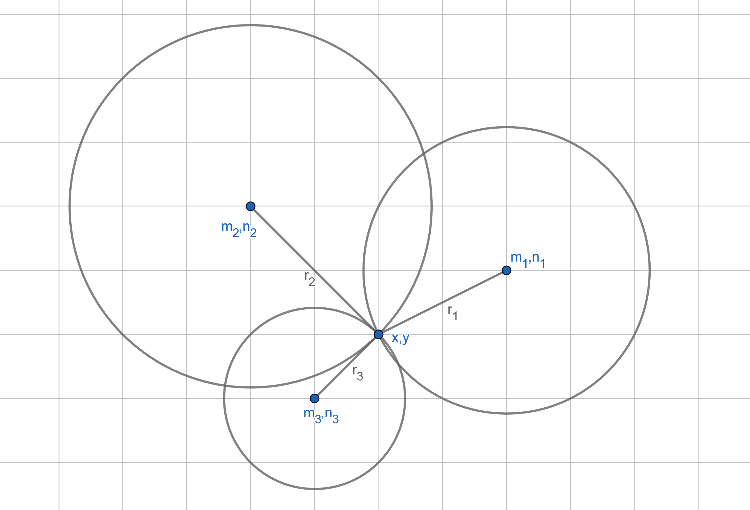
It might look like this. I put the drawing on a grid in order to clearly show the cathetus, showing the distance that is between the centre and the unknown point coordinates.
So close yet so far
In conclusion, we can say that this method is precise. It’s the most precise method we discussed, from an analytical point of view. We need to know precisely the location of the access points. That’s not difficult as we can have such databases accessible in a phone.
We also need to make sure that there are four access points for the signal at each and every location in the building (if the building has several levels). Otherwise, we only need three. This is also easy to do as we don’t need Wi-Fi access points, the Bluetooth beacons will do just fine.
The problem lies in the measurement of the signal’s strength. The fact is that a phone will never accurately measure the strength of the received signal. That’s what makes it difficult. What if the access point is behind a wall? The received signal will be weak and the phone will evaluate it as the access point being far away, let’s say five meters. But in reality, it’s only half a meter away, on the other side of the wall. This method cannot tell the difference.
And that’s why it’s most usable in situations where the army uses it. This method is suitable for use only in open spaces with no obstacles. It’s just not useful in a building full of walls. No method that tries to determine the distance from the transmitter using the received signal is suitable for such buildings.
Conclusion
The last piece of the puzzle will be presented in the final article of this series. The process is very similar when used in a three-dimensional space. We only need to add another dimension to our equation and add it to our system.